As a supplier of Partial Discharge Testers, I’ve witnessed firsthand the crucial role that proper grounding plays in the performance of these instruments. In this blog post, I’ll delve into the various aspects of how the grounding of a Partial Discharge Tester affects its performance, drawing on my experiences and industry knowledge. Partial Discharge Tester
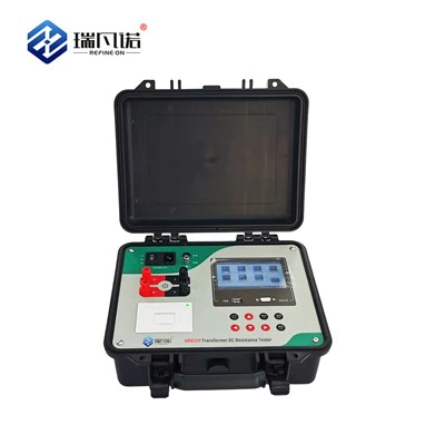
Understanding Partial Discharge Testing
Before we explore the impact of grounding, let’s briefly understand what partial discharge testing is. Partial discharge (PD) refers to the electrical discharge that occurs within a dielectric material, such as insulation in electrical equipment, when the electric field strength exceeds a certain threshold. These discharges can cause progressive damage to the insulation, leading to equipment failure over time. Partial discharge testers are used to detect and measure these discharges, providing valuable information about the condition of the insulation and helping to prevent costly breakdowns.
The Importance of Grounding in Partial Discharge Testing
Grounding is a fundamental aspect of electrical systems, and it plays a critical role in partial discharge testing. A proper ground connection provides a low – impedance path for electrical currents, ensuring the safety of the equipment and the operators. In the context of partial discharge testing, grounding has several key functions:
1. Noise Reduction
One of the primary challenges in partial discharge testing is the presence of electrical noise. Noise can interfere with the accurate detection and measurement of partial discharges, leading to false readings or inaccurate results. A well – grounded partial discharge tester helps to reduce electrical noise by providing a reference point for the electrical signals. The ground connection acts as a sink for unwanted electrical currents, preventing them from coupling into the measurement circuit.
For example, in a high – voltage substation environment, there are numerous sources of electrical noise, such as switching operations, radio frequency interference, and corona discharges. If the partial discharge tester is not properly grounded, these noise sources can easily couple into the measurement system, making it difficult to distinguish between the actual partial discharges and the background noise. By ensuring a good ground connection, the tester can effectively reject the noise and provide more accurate measurements.
2. Safety
Safety is of utmost importance in any electrical testing procedure. A proper ground connection helps to protect the operators and the equipment from electrical hazards. In the event of a fault, such as a short – circuit or a breakdown in the insulation, the ground provides a path for the fault current to flow safely to the earth. This prevents the build – up of dangerous voltages on the equipment and reduces the risk of electric shock to the operators.
When using a partial discharge tester, it is essential to ensure that the ground connection is reliable and meets the relevant safety standards. This includes using proper grounding cables, connectors, and grounding electrodes. Additionally, the grounding system should be regularly inspected and maintained to ensure its integrity.
3. Signal Integrity
In partial discharge testing, the accuracy of the measured signals is crucial. A proper ground connection helps to maintain the integrity of the electrical signals by providing a stable reference potential. Without a stable ground, the electrical signals can be affected by fluctuations in the reference potential, leading to inaccurate measurements.
For instance, if the ground connection is loose or has a high impedance, the electrical signals can experience voltage drops and fluctuations. This can distort the shape and amplitude of the partial discharge signals, making it difficult to accurately analyze and interpret the test results. By ensuring a low – impedance ground connection, the tester can maintain the integrity of the signals and provide more reliable measurements.
Factors Affecting Grounding Performance
Several factors can affect the grounding performance of a partial discharge tester. Understanding these factors is essential for ensuring optimal performance.
1. Grounding Resistance
The grounding resistance is a key parameter that determines the effectiveness of the ground connection. A low grounding resistance is desirable as it provides a low – impedance path for the electrical currents. High grounding resistance can lead to increased voltage drops, reduced noise rejection, and compromised signal integrity.
The grounding resistance is affected by several factors, including the type of soil, the depth of the grounding electrode, and the size of the grounding conductor. In areas with high – resistivity soil, such as sandy or rocky terrain, it may be necessary to use additional grounding electrodes or grounding enhancement materials to reduce the grounding resistance.
2. Grounding Cable and Connector Quality
The quality of the grounding cable and connectors also plays a significant role in the grounding performance. A high – quality grounding cable with low resistance and good insulation properties is essential for ensuring a reliable ground connection. Similarly, the connectors should be properly tightened and have low contact resistance to minimize voltage drops.
Poor – quality grounding cables or connectors can introduce additional resistance into the grounding circuit, leading to reduced grounding performance. Over time, the connectors may also corrode or loosen, further deteriorating the grounding connection.
3. Grounding Electrode Design
The design of the grounding electrode is another important factor. The grounding electrode should be designed to provide a large surface area in contact with the soil to reduce the grounding resistance. Common types of grounding electrodes include rods, plates, and grids.
The choice of grounding electrode depends on several factors, such as the soil conditions, the available space, and the required grounding resistance. In some cases, a combination of different grounding electrodes may be used to achieve the desired grounding performance.
Impact of Improper Grounding on Partial Discharge Tester Performance
Improper grounding can have a significant impact on the performance of a partial discharge tester. Here are some of the common issues that can arise:
1. False Readings
As mentioned earlier, electrical noise can interfere with the accurate detection of partial discharges. If the tester is not properly grounded, the noise levels can increase, leading to false readings. These false readings can give a misleading impression of the insulation condition, potentially leading to unnecessary maintenance or missed faults.
For example, a high – level of background noise can cause the tester to detect signals that are not actually partial discharges. This can result in false alarms and wasted resources on further investigation.
2. Inaccurate Measurements
Improper grounding can also lead to inaccurate measurements of the partial discharge magnitude and frequency. The voltage drops and fluctuations caused by a poor ground connection can distort the shape and amplitude of the partial discharge signals, making it difficult to accurately measure these parameters.
Inaccurate measurements can have serious consequences, as they can lead to incorrect assessments of the insulation condition. This can result in either over – maintenance or under – maintenance of the electrical equipment, both of which can be costly.
3. Equipment Damage
In some cases, improper grounding can cause damage to the partial discharge tester itself. High – voltage surges or electrical transients can occur in the electrical system, and if the tester is not properly grounded, these surges can be transferred to the tester, causing damage to its internal components.
This can lead to costly repairs or even the need to replace the tester. Additionally, damaged equipment may provide unreliable test results, further compromising the integrity of the insulation assessment.
Ensuring Proper Grounding for Optimal Performance
To ensure the optimal performance of a partial discharge tester, it is essential to pay attention to the grounding requirements. Here are some best practices:
1. Conduct a Grounding Resistance Test
Before using the partial discharge tester, it is recommended to conduct a grounding resistance test to ensure that the grounding resistance is within the acceptable range. This can be done using a grounding resistance tester. If the grounding resistance is too high, steps should be taken to reduce it, such as adding additional grounding electrodes or using grounding enhancement materials.
2. Use High – Quality Grounding Components
Invest in high – quality grounding cables, connectors, and grounding electrodes. Ensure that the cables have low resistance and good insulation properties, and that the connectors are properly tightened and have low contact resistance. Regularly inspect the grounding components for signs of damage or corrosion and replace them as needed.
3. Follow Manufacturer’s Guidelines
The manufacturer of the partial discharge tester usually provides specific guidelines for grounding. It is important to follow these guidelines carefully to ensure that the tester is properly grounded. These guidelines may include information on the type of grounding cable to use, the grounding electrode design, and the recommended grounding resistance.
Conclusion

In conclusion, the grounding of a partial discharge tester has a profound impact on its performance. Proper grounding is essential for noise reduction, safety, and signal integrity. By understanding the factors that affect grounding performance and taking the necessary steps to ensure proper grounding, we can improve the accuracy and reliability of partial discharge testing.
Cable Tester As a supplier of partial discharge testers, we are committed to providing our customers with high – quality products and technical support. If you are interested in purchasing a partial discharge tester or have any questions about grounding or partial discharge testing, please feel free to contact us for further discussion. We look forward to working with you to ensure the optimal performance of your electrical equipment.
References
- IEEE Std 400.2 – 2013, IEEE Guide for Field Testing and Monitoring of the Insulation of Shielded Power Cables.
- IEC 60270:2000, High – voltage test techniques – Partial discharge measurements.
- A. E. Davies, “Partial Discharge Detection and Measurement,” in Electrical Insulation and Dielectric Phenomena, pp. 397 – 423, 2004.
Refine On (Hebei) Electric Power Technology Co., Ltd.
Refine On (Hebei) Electric Power Technology Co., Ltd. is one of the most reliable partial discharge tester manufacturers and suppliers in China, also supports customized service. Please feel free to wholesale advanced partial discharge tester at competitive price from our factory. Contact us for quotation.
Address: Building 13, Liandong U Valley, No.64, Jing SAN South Street, Economic Development Zone, Mancheng District, Baoding City, China
E-mail: victor@transformer-test.com
WebSite: https://www.transformer-test.com/
