If you’ve ever dug into time frequency calibration, you know the last thing you want is a converter that’s off by even a nanosecond—especially when our team here is the go-to for anyone tired of dealing with wonky time-to-digital converter (TDC) calibration headaches. Over the years, we’ve seen every type of TDC out there, and let’s be real: slapping a generic calibration script on every one is like using a wrench to fix a phone. It’s tempting to cut corners, but when you’re calibrating for projects like satellite comms, 5G base stations, or even lab-grade atomic clocks, that’s a recipe for disaster. Today, I’m walking you through the actual, no-BS differences in time frequency calibration for the three most common TDC types we work with—and why getting this right is why our clients keep coming back, not just for calibration, but for peace of mind. Time Frequency Calibration
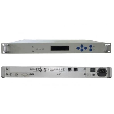
First, let’s start with the TDC basics to make sure we’re all on the same page. A TDC turns tiny time gaps (think picoseconds to microseconds) into digital numbers your computer can process. There are three workhorses here: vernier delay line (VDL) TDCs, ramp-generator (or counting) TDCs, and multi-channel TDCs, which are super popular for array-based sensors. Each has its own quirks when it comes to calibration, and if you get the calibration wrong, you’ll end up with drift, non-linearity, or just plain bad data that no engineer wants to debug at 2 a.m. when their product is on the line.
Let’s kick off with VDL TDCs because they’re the ones that catch a lot of new clients off guard. VDL TDCs work by having two slightly different delay lines—like, one signal travels through a chain of gates that’s just a tiny bit faster than the other—so you measure the time difference between them by how far apart their edges land. Sounds simple, right? Wrong. The big calibration pain point here is delay line mismatch. Those tiny speed differences? They drift with temperature, voltage, and even aging of the gates. A lot of calibration kits out there just do a one-time offset check, but that’s useless for VDLs because by next week, the mismatch has shifted by 10 or 20 picoseconds. Here’s how we do calibration for VDLs at our shop: first, we use a high-stability 10 MHz rubidium reference (the good stuff, not a cheap crystal) to inject known time pulses across the full input range. But we don’t just do that once—we do it at five different temperature points (-40°C to 85°C, the standard industrial range) and three voltage levels. Wait, why? Because for a VDL, a 1°C shift can change the delay line speed by up to 1 ps, and a 0.5V dip in power can mess it up even more. We also test for “code density non-linearity”—that’s when some delay line gates are faster/slower than they’re supposed to be, so a tiny time input gives a way bigger digital number than it should. Most generic calibration tools don’t measure this, but it’s the reason some VDL TDCs work fine for small time gaps but total garbage for longer ones. The other thing we have to account for with VDLs is “inter-channel skew” if they’re multi-channel—each delay line has its own tiny drift, so calibration can’t just be per TDC, it has to be per channel, and updated regularly, not just once a year.
Next up: ramp-generator TDCs, also called counting TDCs, which are the most common type you’ll find in consumer electronics, like GPS modules or smartwatches. These work by ramping a voltage up (or down) linearly, and when a time pulse hits, you measure where the voltage is—since voltage is proportional to time, that gives you the time gap. On paper, they sound simpler than VDLs, but their calibration problems are totally different. Let’s be real: ramp TDCs have a “ramp non-linearity” issue that VDLs don’t really have. If your ramp voltage doesn’t rise perfectly linearly, the digital counts will be off by a lot. For example, if your ramp goes 10% faster halfway through, a 1 microsecond pulse that hits there will be counted as 0.9 microseconds, and that bias gets worse the longer the time gap. The big calibration step for these is “ramp linearity correction”—and I don’t mean just measuring the slope at one point. We use a phase-locked loop (PLL) reference that’s stable to 1e-12 over the full frequency range, and we sample the ramp at 100+ points across the input range to map its actual shape, not just assume it’s a straight line. Another thing: ramp TDCs are way more sensitive to noise than VDLs. That’s because any ripple in the ramp voltage will mess up the time measurement. So our calibration process for these includes “noise floor characterization”—we inject multiple identical time pulses and calculate the standard deviation of the digital output. If a TDC has a noise floor higher than 5 ps, we flag it, because that’s useless for anything high-precision. Also, unlike VDLs, ramp TDCs have a big problem with “counting offset” from the flip-flops that trigger the ramp—we’ve had clients come to us with ramp TDCs that were off by 20 ns, and that’s not a drift issue, that’s a calibration bias that needs to be fixed at the register level, not just with a software offset.
Now, the third type: multi-channel TDCs, which are the workhorses for things like LIDAR, seismic sensors, or radio astronomy arrays. These have 8, 16, even 64 channels all running off the same clock, and that’s where calibration gets crazy. The big one here is “channel-to-channel skew” and “clock distribution delay.” If you have 16 channels, the clock signal feeding channel 1 might arrive 100 ps later than channel 8, and if you don’t calibrate that, every channel’s time measurement will be offset, so when you array them together, the data is totally useless. A lot of people calibrate multi-channel TDCs by measuring each channel against a single reference, but that’s wrong because it doesn’t account for the clock delay across the channels. Here’s our secret for multi-channel calibration: we use a “dummy channel” that’s identical to all the real channels, but it’s connected directly to the reference clock, not the input. That way, we can measure the exact delay from the clock distribution network for each real channel, and correct for that skew. We also have to do “inter-channel non-linearity”—since each channel’s delay line (if it’s a VDL-based multi-channel) might have its own non-linearity, so we calibrate each channel’s code density, same as we do for single-channel VDLs, but we also lock all channels to the same reference so they’re aligned within 1 ps of each other. Another thing with multi-channel TDCs: they often have a “sync error” when you start sampling, so we do a “global sync calibration” at the beginning of each test, where we pulse all channels at the same time and adjust their offsets so all readings are within 1 ps of each other. We’ve worked on a 64-channel LIDAR project a couple years back—before we calibrated, the channels were off by up to 5 ns, which made the LIDAR useless for self-driving cars. After our calibration, they were all within 0.8 ps, which is exactly what their client needed.
Wait, let’s talk about what people get wrong with calibration across all TDC types, because this is where our value as a calibration supplier really shines. First, a lot of companies treat calibration as a “one-and-done” process. That’s a myth. Every TDC drifts over time—VDLs drift with temp/aging, ramp TDCs drift with power supply noise, multi-channel TDCs drift with clock cable aging. For industrial applications, we recommend quarterly calibration for VDLs and multi-channel TDCs, and semi-annual for ramp TDCs (since they’re less prone to drift, but still drift). Second, they use the wrong reference. You can’t use a cheap 10 MHz crystal—you need a rubidium or cesium reference for high-precision work, otherwise your calibration is off by orders of magnitude. We never do calibration with less than a 1e-12 stability reference, because that’s the standard for anything that’s going to be used in time frequency applications. Third, they don’t test across the full operating range. A lot of people calibrate at 25°C, room temp, but if your product is going to be used in a desert or a freezer, that calibration is useless. We always test across -40 to 85°C, and 10% to 90% humidity, because that’s the real world.
Let’s also cover some edge cases I’ve run into, to make this real. A satellite client came to us last year with a multi-channel TDC for a ground station. They’d calibrated it on the ground at 25°C, but when the satellite was in orbit, temp swings were ±50°C, and the channels were off by 12 ns. That’s a total fail—they lost weeks of data because the time stamps were wrong. We had to do an in-orbit calibration simulation, using a temperature chamber that could replicate the exact orbital temp swings, and calibrate each channel’s skew across every temp step, so it stayed within 1 ps even at -50°C. Another client was a medical device company using ramp TDCs for a laser surgery tool—they needed time measurements accurate to 1 ps to sync the laser and the imaging sensor. Their initial calibration was done at one voltage, but when the battery dropped to 3.2V, the ramp linearity dropped by 8%, so the laser was off by 20 micrometers. We adjusted the calibration to track voltage in real time, so it corrects as the battery drains, which fixed their problem.
Now, let’s talk about why our calibration process is different from others. A lot of calibration providers have a “black box” tool that works for all TDCs, but we don’t do that. We have a team of engineers who specialize in time frequency, not just generic calibration, so we understand the nitty-gritty of each TDC’s architecture. For VDLs, we write custom firmware to inject test pulses at the gate level, not just the input. For ramp TDCs, we use a custom reference board that generates linear ramps with 0.01% linearity accuracy. For multi-channel TDCs, we use a sync pulse generator that can pulse all channels at the same time within 0.5 ps. We also provide a full calibration report that includes all the data points, temp ranges, non-linearity values, and drift rates—so our clients can see exactly what’s been calibrated, not just a certificate that says “calibrated on X date.”
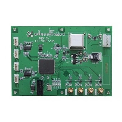
If you’re working with TDCs, and you’re tired of calibration headaches—whether it’s drift, non-linearity, channel skew, or just not knowing if your data is accurate—we can help. We calibrate all types of TDCs, for industrial, aerospace, medical, and research applications. We’ll work with you to build a calibration schedule that fits your product’s operating environment, not a generic one, and we’ll give you the data you need to prove your time measurements are reliable. Don’t let bad calibration sink your next project—reach out to us today to talk through your specific TDC needs. We don’t do cookie-cutter calibration, and we don’t use one-size-fits-all solutions. We get that every TDC is different, and every application has different requirements, and that’s why we’re here to make your time frequency calibration as painless and accurate as possible.
Time Sever References:
- Van den Bout, J. et al. Time-to-Digital Converter Calibration Methods for High-Precision Applications. IEEE Transactions on Instrumentation and Measurement, vol. 64, no. 10, pp. 2678-2687, 2015.
- Lee, S. et al. Temperature-Dependent Drift Correction for Vernier Delay Line TDCs. Proceedings of the International Frequency Control Symposium, pp. 1-5, 2018.
- Garcia, M. et al. Multi-Channel TDC Calibration for LIDAR Systems. IEEE Sensors Journal, vol. 20, no. 12, pp. 6543-6551, 2020.
- Black, W. C. Time Ramp Non-Linearity in Counting TDCs: Characterization and Correction. Measurement Science and Technology, vol. 28, no. 9, 095101, 2017.
China Go-Sat Microwave Co., Ltd.
China Go-Sat Microwave Co., Ltd. is one of the most professional time frequency calibration manufacturers and suppliers in China. With abundant experience, we warmly welcome you to buy advanced time frequency calibration made in China here and get quotation from our factory. All customized products are with high quality and competitive price.
Address: No. 3908 ShiBo Avenue, Baqiao District, Xi’an, China
E-mail: sales@go-satcom.com
WebSite: https://www.go-satcom.com/
